


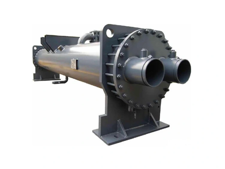
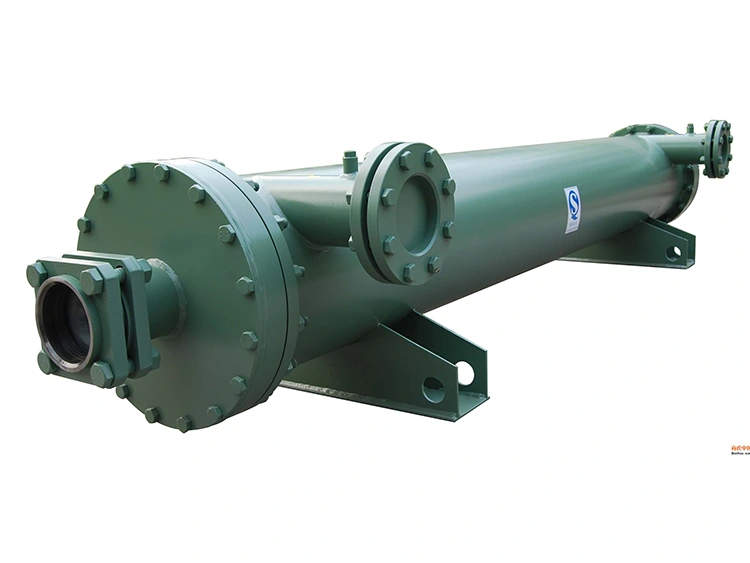
Shell-and-tube Evaporator
The Shell-and-tube Evaporator, designed and manufactured by leading China-based supplier Lynxcool, is a high-performance heat exchanger used as the primary evaporator in industrial refrigeration systems. Suitable for medium to large-scale systems above 50 kW, it handles a wide range of process fluids, from chilled water and glycol to complex industrial liquids.
The Lynxcool Shell-and-tube Evaporator is the preferred evaporator for industrial refrigeration and process cooling applications exceeding 50 kW. Compared with plate or spiral-tube evaporators, its high thermal mass, corrosion resistance, and robust design ensure stable operation under demanding conditions. Whether applied in cold storage, food processing, chemical, or pharmaceutical cooling, the evaporator delivers reliable performance while minimizing downtime and maintenance costs.
Key Advantages
The Lynxcool Shell-and-tube Evaporator excels in heat transfer efficiency, material flexibility, and long service life. Its design supports multi-refrigerant compatibility (NH₃, CO₂, HFC, HFO blends), rapid on-site installation, OEM replacement, and low maintenance. Factory-applied insulation and coatings reduce installation labor and ensure consistent thermal performance.
Core Technical Features
Flooded vs. DX Shell-Side Design
Flooded evaporators fully submerge the tube bundle in liquid refrigerant, increasing the wetted area and heat transfer coefficients by 20–35%, making them ideal for ammonia and large HFC systems. DX (direct-expansion) configurations use a minimal refrigerant charge, suitable for CO₂ low-GWP systems and modular chillers, balancing refrigerant inventory control and safety requirements.
Tube Bundle Optimization
Standard copper tubes feature an internal micro-fin profile to increase heat transfer surface area by 60–80% and maintain turbulent flow even at low Reynolds numbers. The external surface is configured with low fins or smooth tubing depending on the refrigerant type, optimizing nucleate boiling efficiency. For ammonia applications, smooth external tubes prevent liquid entrainment and improve bubble departure.
Pressure Vessel Compliance
The shells of the Lynxcool Shell-and-tube Evaporator are fabricated from Q345R or SA-516 Gr.70 certified steel, with longitudinal welds radiographically inspected (RT Grade II) and hydrostatically tested at 1.25× design pressure. Tube-to-tube sheet joints are roller-expanded and seal-welded for ammonia service. Third-party inspections (CCS, TÜV, Bureau Veritas) are available upon request.
Material and Corrosion Resistance
Tube material is selected based on process fluid: TP2 copper for clean chilled water, 316L stainless steel for mild acids or food-grade circuits, Titanium Grade 2 for seawater or aggressive chemicals, and Cupronickel 90/10 for marine applications. Tube sheets are matched to tube alloys to prevent galvanic corrosion.
Technical Parameters
|
Parameter |
Value / Range |
|
Cooling Capacity Range |
50 kW – 5,000 kW (custom beyond range on request) |
|
Shell Diameter |
DN 200 – DN 1,600 mm |
|
Effective Tube Length |
1,500 – 6,000 mm (standard); longer on request |
|
Number of Tube Passes |
1, 2, or 4 pass (application-specific) |
|
Tube Material (Standard) |
Seamless copper (TP2 / C12200) |
|
Tube Material (Options) |
Stainless steel 316L, titanium Gr.2, cupronickel 90/10 |
|
Tube OD × Wall Thickness |
19.05 mm × 1.2 mm / 25.4 mm × 1.5 mm (standard) |
|
Tube Surface Enhancement |
Internally grooved (micro-fin), externally low-fin or smooth |
|
Shell Material |
Carbon steel Q345R (GB 151) or SA-516 Gr.70 (ASME) |
|
Shell-Side Fluid |
Refrigerant — flooded or DX expansion |
|
Tube-Side Fluid |
Chilled water, brine, ethylene / propylene glycol, process liquid |
|
Design Pressure — Shell Side |
≤ 4.0 MPa (standard); ≤ 12 MPa (CO₂ high-pressure) |
|
Design Pressure — Tube Side |
≤ 2.5 MPa (standard) |
|
Design Temperature Range |
-60 °C to +150 °C (material-dependent) |
|
Evaporating Temperature Range |
-55 °C to +10 °C |
|
Refrigerant Inlet Connection |
Flanged DN 25 – DN 200, PN 16 / PN 40 |
|
Process Fluid Connections |
Flanged or grooved, DN 50 – DN 400 |
|
Insulation (Standard) |
50 mm closed-cell polyurethane foam, factory-applied |
|
Pressure Test Standard |
1.25× design pressure hydrostatic, per GB 151 / ASME VIII |
|
Design & Fabrication Code |
GB 151 / GB 150 (standard); ASME VIII Div.1; PED 2014/68/EU |
|
Compatible Refrigerants |
R717 (NH₃), R744 (CO₂), R22, R134a, R404A, R507A, R410A, R448A, R449A |
|
Finish & Coating |
Internal: clean passivated; External: epoxy primer + polyurethane topcoat |
|
Quality Certification |
ISO 9001 · CE · PED · GB 150 pressure vessel certificate |
Applications and Target Users
The Lynxcool Shell-and-tube Evaporator is a versatile solution for industrial, commercial, and district cooling applications, providing reliable performance, high heat-transfer efficiency, and long-term durability. It is designed to meet the needs of industries with demanding cooling requirements while ensuring adaptability to various process fluids and refrigerants.
Industrial Refrigeration
The evaporator is ideal for:
● Cold storage warehouses – providing stable low-temperature cooling for large-scale storage.
● Spiral freezers – maintaining uniform temperature in continuous freezing processes.
● Packaged ammonia screw chillers – supporting high-capacity industrial refrigeration systems.
● CO₂ transcritical systems – handling high-pressure, low-GWP refrigeration with safety and efficiency.
Process Cooling
Applications include:
● Chemical reactor jacket cooling – compatible with aggressive chemicals using 316L stainless steel or Titanium Grade 2.
● Plastic injection molding and extrusion lines – precise temperature control for manufacturing processes.
● Food and beverage fermentation tanks – ensuring consistent cooling for high-quality production.
● Pharmaceutical clean-room loops – maintaining GMP-compliant cooling for sensitive processes.
HVAC and District Cooling
● OEM chiller barrel replacements – drop-in replacements for large centrifugal and screw chillers.
● Standalone district cooling heat exchangers – efficient water-to-water or refrigerant-to-water heat transfer.
● Hybrid free-cooling circuits – high-pressure hot-water recovery and low-energy cooling solutions.
Overall, the Lynxcool Shell-and-tube Evaporator combines adaptability, material flexibility, and high-efficiency heat transfer, making it an ideal choice for industrial and commercial systems that demand reliability and long-term operational stability.

After-Sales Service
Lynxcool provides comprehensive after-sales support to ensure long-term, reliable operation:
● Technical Support: Thermal calculations, fluid compatibility checks, and tube material recommendations
● Installation Guidance: On-site or remote support to ensure proper connections and sealing
● Commissioning Assistance: Pre-startup testing and performance validation
● Regular Maintenance: Annual inspections, tube cleaning, and preventative maintenance guidance
● Spare Parts Supply: Long-term availability of original components
● Remote Monitoring: Operational data analysis and troubleshooting
● Emergency Response: 24-hour rapid response for critical equipment issues
FAQ
Q: What is the difference between a flooded and DX evaporator?
A: Flooded designs immerse the tube bundle in liquid refrigerant, increasing heat transfer by 20–35%, ideal for ammonia and large HFC systems. DX designs use minimal refrigerant, suitable for CO₂ low-GWP systems or modular chillers.
Q: How should I select tube material for my process fluid?
A: Clean water or glycol: TP2 copper. Mild acids or food-grade fluids: 316L stainless steel. Seawater or corrosive fluids: Titanium Grade 2. Lynxcool engineers verify compatibility before fabrication.
Q: Can Lynxcool manufacture replacement barrels for existing OEM chillers?
A: Yes — providing nameplate and flange drawings allows a direct drop-in replacement of the Lynxcool Shell-and-tube Evaporator, with typical delivery in 8–12 weeks and minimal downtime.
Q: Is the insulation removable for maintenance?
A: Yes, factory-applied PU foam has removable end covers, allowing tube bundle inspection and cleaning without refrigerant recovery.
Q: What is the lead time and documentation package?
A: Standard units: 4–6 weeks. Large or special-material units: 8–14 weeks. Documentation includes GA drawings, thermal datasheets, MTRs, weld maps, radiographic and hydrostatic test reports, packing list, and third-party certificates if required.
Hot Tags: Shell-and-tube Evaporator, China supplier, refrigeration evaporator, industrial heat exchanger
Send Inquiry
Contact Info
-
Address
No. 1 Zhengzhou Road, Shibei District, Qingdao City, Shandong Province, China
-
Tel
-
E-mail
Welcome to send your detailed demands for Refrigeration Compressor Unit, Screw Compressor Unit, Evaporator. Our professional sales team from this China refrigeration manufacturer will reply quickly, provide custom plans and one-stop purchasing service.


